Monday, 7 October 2019

Verilog code for PWM Generator

Pulse Width Generator Model
PWM.v

module pwm(clk_in,sw0,rst,sine_ampl,div_factor_freqhigh,div_factor_freqlow,pwm_out);

parameter width_p = 10'd12;                                             

input clk_in;

input rst;                                                          

input sw0;

input [width_p-1:0] sine_ampl;                                        

input [31:0] div_factor_freqhigh;                                     

input [31:0] div_factor_freqlow;                                      

output reg pwm_out;                                                    

parameter load_new_ampl = 3'd0;

parameter pwm_high = 3'd1;

parameter pwm_low = 3'd2;

wire ce_w;                                                          

reg [2:0]state_r;                                                     

reg [2:0]n_state;                                                                    

reg [12:0]treshold_r =20'd0;

reg [12:0]count_r = 20'd0;

frequency_trigger freq_ce (clk_in, sw0, div_factor_freqhigh, div_factor_freqlow, ce_w);

always @ (posedge clk_in or posedge rst)

 begin

  if(rst)

  state_r<=load_new_ampl;

  else

  state_r  0)

   n_state <= pwm_high;

   else if (sine_ampl == 0)

   n_state <= pwm_low;

 end

pwm_high:

 begin

  count_r = count_r + 1;                                        

   if ((count_r <((2**width_p)-1)) && (count_r < treshold_r))

    n_state <= pwm_high;

   else if (count_r == (2**width_p)-1)

    n_state <= load_new_ampl;

   else if (count_r < ((2**width_p)-1) && (count_r == treshold_r))

   n_state <= pwm_low;

 end

 pwm_low:

  begin

  count_r = count_r +1;                                           

  if (count_r < ((2**width_p)-1))

  n_state <= pwm_low;

  else if (count_r == ((2**width_p)-1))

  n_state <= load_new_ampl;

 end

endcase

end


always @(posedge clk_in)

begin

 case (state_r)

 load_new_ampl: pwm_out = 0;

 pwm_high: pwm_out = 1;

 pwm_low: pwm_out = 0;

 endcase

end

endmodule

===================================

frequency_trigger.v

frequency_trigger(clk_in,sw0,div_factor_freqhigh,div_factor_freqlow,freq_trig);

input clk_in;                       

input sw0;                       

input [31:0] div_factor_freqhigh;

input [31:0] div_factor_freqlow;

output reg freq_trig;            

 integer freq_cnt=12'd0;          

 always @(posedge clk_in)

  begin

   freq_trig = 1'b0;             

   freq_cnt = freq_cnt + 1;    

  if (sw0 == 0)

   begin

   if (freq_cnt >= div_factor_freqlow -1)

    begin

    freq_trig = 1'b1;

    freq_cnt = 'd0; //reset

   end

  end

  else

  begin

  if (freq_cnt >= div_factor_freqhigh - 1)

  begin

  freq_trig = 1'b1;

  freq_cnt = 'd0; //reset

  end

 end

end

endmodule

==============================

Finally we need test bench to run the simultions and check the functionality of the design

pwm_testbench.v

module pwm1_tb();

parameter cntampl_value_p = 8'hff;           

parameter depth_p = 8'd8;                      

parameter width_p = 10'd12;                  

reg clk_in_r;

reg rst_r;                                   

reg sw0_r;                                     

reg [(width_p-1):0] sine_out_w;                    

wire pwm_out_w;                                  

  pwm dut2 (clk_in_r, sw0_r,rst_r,sine_out_w, 1, 2, pwm_out_w);

initial

begin

rst_r=1'b1;

clk_in_r = 1'b1;

 end

 always #10 clk_in_r = ~clk_in_r;

initial

begin

#50000 rst_r=1'b0;

 sw0_r = 1'b0;

 sine_out_w=3000;

 #163860  sine_out_w=4220;

 #163860 sine_out_w=2376;

 #163860 sine_out_w=5856;

 #163860 sine_out_w=1237;

 #163860 sine_out_w=5856;

 #163860 sine_out_w=5984;

 #163860 sine_out_w=5598;

 #163860 sine_out_w=4763;

 #163860 sine_out_w=3624;

 #163860 sine_out_w=2376;

 #163860 sine_out_w=1237;

 #163860 sine_out_w=402;

 #163860  sine_out_w=16;

 #163860 sine_out_w=147;

 #163860 sine_out_w=771;

 #163860 sine_out_w=1780;

 #163860 sine_out_w=3000;

 end

initial

#200000000 $finish;

endmodule

================================

Digitally Controlled PWM Generator

Design specification
Design and implementation of  architecture of Frequency trigger, Finite State Machine (FSM) for generating the PWM signal ,Pulse Width Modulation.
Input   :  clk,
Input   : [11:0]sin amp
Input   : switch0,fmhigh,fmlow.
Output: [1:0] pwm

Depending upon frequency high(fmhigh), frequency low(fmlow),frequency trigger will generate different  waveforms. By using fsm we design  Pwm model. 

Architecture for the design specification 

                                                             Fig 1: FSM
                                                       Fig 2: Block diagram

 Manual calculation
PWM is modulation technique used to encode a message into a pulsing signal. In PWM Ton denotes the one time and Toff denotes the off time of signal. Period is the sum of both on and off times and is calculated as shown below.

  Ttotal =Ton +Toff

Duty cycle is calculated as on time to the period and duty is calculated as below

D=Ton /(Ton + Toff)
 D= Ton/Ttotal

PWM Signal when used at a different duty cycles gives a varying voltage at the output. This method is used in various applications like:

  • Switching regulators
  • Led dimmers
  • Audio
  • Analog signal generation
  • Speed control of Motors

The out voltage is calculated by following equations

Vout  = D*Vin
Vout =(Ton /Ttotal)*Vin

  verilog code in next post      

Sunday, 6 October 2019

VIM editor series I

Search A Pattern

  • Press Esc
  • Then type / or ? and the pattern need to search

To do Substitution

:%s/Old String/New String/g 

Converting the Tab to Spaces

:set expandtab 


To control the number of space character need to be inserted when the tab was used

:set tabstop=4 

After the expandtab option is set all the new tab characters entered will be changed to spaces. This will not affect the exiting tab characters. To change all the existing tab characters to match the current tab settings use

:retab 

Display the line numbers
enable the line number

:set number or :set nu 

disable the line numbers

:set nonumber or :set nonu 

Reversing the Order of lines

:g/^/m0


:—- start the command line mode
g—- action will be taken all lines in the files
^—-matches the starting of the line
m—moves the elements
0—Is the destination line, beginning of the buffer

If i need to reverse the lines between a certain range(like between 30 and 40 lines), then we can use the following command

:30,40g/^/m29 

To control the position of split window

:set splitbelow or splitright 

Undo and Redo
        In normal mode conditions

  • use u for undo the action
  • cntrl+r for redo the action        

Saturday, 5 October 2019

Perl_Series II

Hashes
A hash is an un-ordered group of KEY-VALUE pairs and keys are unique strings(duplication of keys are not allowed). The values are scalar and they can be either a number ,a string or a reference. These are also called as associative arrays.

Before using the hash we have to first declare it 

my %hash ;

As I said above duplication of keys are not allowed and this property can be used to list out the elements without any repetition. Let us consider a array of numbers with repetition.
@numbers =(0,2,3,4,1,4,2,2,3,5,5)

my @unique;
my %hashes;
my @numbers =(0,2,3,4,1,4,2,2,3,5,5);
foreach my $value (@numbers) {
  if (! $hashes{$value}) {    
push @unique, $value;   $hashes{$value} = 1; 
}}
print @unique;

output:023415

Friday, 4 October 2019

Perl_Series I

Assume the file contains 10 words and we need to find the longest word and print on the console with help of perl script. Following are different ways to open a file and read the content using perl

  • less than < sign indicates that file has to be opend in read-only mode.
    open(DATA, “<vlsispace.txt”)
  • greater than > sign indicates that file has to be opend in the writing mode.
    open(DATA, “>vlsispace.txt”)
  • To open a file for updating without truncating it 
    open(DATA, “+<vlsispace.txt”)
  • To truncate the file first 
    open DATA, “+>vlsispace.txt”
  • In this mode, writing point will be set to the end of the file and append new data to file
    open(DATA,”>>vlsispace.txt”)
  • To read the data in a file during append process
    open(DATA,”+>>vlsispace.txt”)

#!usr/bin/perl
open r,”<data.txt” or “cannot open the file”;
@string_words;
while($a=<r>)
{
chomp($a);
$i++;
@string_words[$i]=$a;
}
foreach $d(@string_words)
{
$i=length($d);
if($max<$i)
{
$word=$d;
$max=$i;
}
}
print “@string_words\n”;
print “the longest word:$word\n”;
print “the length of the longest word:$max\n”;
close r;

Tuesday, 1 October 2019

Cell Delay of Standard Cell and what are the factors effecting the cell delay

Cell Delay:
Time between a 50% transition on input to 50% transition of output waveform. It is also called as

  • Gate delay
  • Propagation delay
                                                      Cell Delay

The gate/cell delay is not constant for all design environmental conditions. Cell delays are calculated using Non Linear Delay Model(NLDM) and the cell/gate delay depends on the input transition and output load

cell delay ={input transition time,Output load}

Input Transition Time :
Time taken by signal to reach 20% to 80% of peak value(rise signal)  or to reach 80% to 20% of peak value(falling signal)

                                       Transition time (rise & fall)

Output Load:
Output load is total capacitance value that is connected to output pin of the cell

 Cload =Cnet+Cpin

Cpin —————-Input capacitance of the driving pin
Cnet —————–Intterconnect capcitance
All this values(input transition time and output load) are provided in lib(timing libray) files of the standard cells and below is snippet of .lib files.


***********snippet of lib file of as standard cell*********************
pin(“PhyInitSync[1]”) {
related_power_pin : VDD;
related_ground_pin : VSS;
direction : input ;
max_transition : 0.150000 ;
capacitance : 0.001672 ;
/* Other user defined attributes. */
original_pin : PhyInitSync[1];
 timing () {
  related_pin : “DfiClk” ;
timing_type : setup_rising ;
rise_constraint( f_dtrans_ctrans ){
index_1 ( “
0.001000, 0.010000, 0.020000, 0.040000, 0.080000, 0.120000, 0.150000″);
index_2 ( “
0.000000, 0.002388, 0.004669, 0.010000, 0.017848, 0.034895, 0.090000″);
values ( “
-0.001922, -0.002219, -0.002587, -0.003267, -0.003591, -0.003837, -0.003263″,\
“0.000255, -4.09999999999994e-05, -0.000410000000000001, -0.00109, -0.001414, -0.001659, -0.001086”,\
“0.001887, 0.00159, 0.001222, 0.000542000000000001, 0.000217, -2.80000000000002e-05, 0.000546”,\
“0.003733, 0.003436, 0.003068, 0.002387, 0.002063, 0.001818, 0.002392″,\
“0.005476, 0.00518, 0.004811, 0.004131, 0.003807, 0.003562, 0.004135”,\
“0.006344, 0.006047, 0.005679, 0.004998, 0.004674, 0.004429, 0.005003”,\
“0.00663, 0.006333, 0.005965, 0.005284, 0.00496, 0.004715, 0.005289”);
}
fall_constraint( f_dtrans_ctrans ){
index_1 ( “
0.001000, 0.010000, 0.020000, 0.040000, 0.080000, 0.120000, 0.150000″);
 index_2 ( “
0.000000, 0.002388, 0.004669, 0.010000, 0.017848, 0.034895, 0.090000″);
values ( “
0.0075, 0.007203, 0.006834, 0.006154, 0.00583, 0.005585, 0.006158″,\
“0.010092, 0.009795, 0.009427, 0.008747, 0.008422, 0.008177, 0.008751”,\
0.012482, 0.012185, 0.011816, 0.011136, 0.010812, 0.010567, 0.01114″,\
0.012482, 0.012185, 0.011816, 0.011136, 0.010812, 0.010567, 0.01114″,\
 “0.015991, 0.015694, 0.015325, 0.014645, 0.014321, 0.014076, 0.014649”,\
………………….
………………….
………………….
}}

For corresponding output load and input transition we can get the cell delay values from the tables provided in the .lib files. Index 1 represents the input transition ,Index 2 represents the output load and the values represents the delay of the cell. Lets us see how does the tool picks the delay value from the NLDM table

Assume the input transition as 0.02 and the output load as 0.01 for particular environment/corner and the value marked red in the values table gives the cell delay(0.003068) for the given input transition and output load. Have u guys noticed above rise_constraint and fall_constraint table, we can calculate the cell delay from both the tables.Then which cell delay value does the tool pick for the analysis  ?

For the setup analysis mode the tool picks which ever cell_delay value is max .
For the Hold analysis mode the tool picks which ever cell_delay value is min .


Up or Down counter which is better

Up Counter:
The counter which counts from 0 to finite value
Down Counter:
The counter which counts from finite value to 0

For a Design if both up and down counter works equally well, then which one should be selected?
Up counter will be the best option compared to the Down counter because we need a two’s complement circuit in down counter which takes extra logic. This increases the no of gates and power consumption.

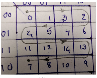
In grey counter only one bit is toggled at each time and this counter is used in pointing the memory locations and simple way to remember the grey count seqeunce


4-bit grey Counter
0000 – 0                                1101 – 12
0001 – 1                                1111 – 14
0011 – 3                                1110 – 13
0010 – 2                                1010 – 9
0110 – 6                                1011 – 10
0111 – 7                                1001 – 8
0101 – 5                                1000 – 7
0100 – 4
1100 – 11


Physical Cells :TAP CELLS, TIE CELLS, ENDCAP CELLS, DECAP CELLS

Tap Cells (Well Taps) :  These library cells connect the power and ground connections to the substrate and n­wells, respectively.  By plac...